 2024/7/3 11:20:05
 206
206
· Support Mixed-Mode Signal Operation (5-V Input and Output Voltages With 3.3-V VCC) Typical VOLP (Output Ground Bounce)
· Typical VOLP (Output Ground Bounce)<0.8 V at VCC = 3.3 V, TA = 25°C
· Support Unregulated Battery Operation Down to 2.7 V
· Ioff and Power-Up 3-State Support Hot Insertion
· Bus Hold on Data Inputs Eliminates the Need for External Pullup/Pulldown Resistors
· Latch-Up Performance Exceeds 500 mA Per JESD 17
· ESD Protection Exceeds JESD 22
− 2000-V Human-Body Model (A114-A)
− 200-V Machine Model (A115-A)
description/ordering information
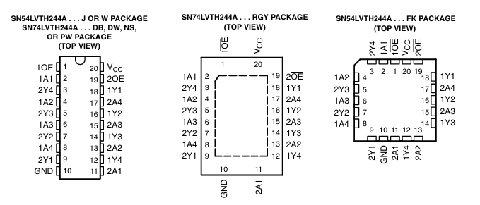
These octal buffers and line drivers are designed specifically for low-voltage (3.3-V) VCC operation, but with the capability to provide a TTL interface to a 5-V system environment.
description/ordering information (continued)
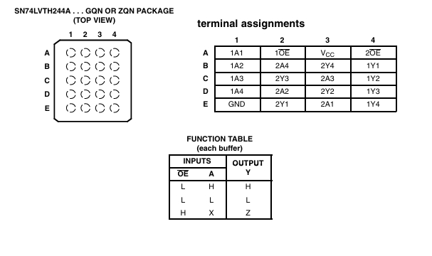
The ’LVTH244A devices are organized as two 4-bit line drivers with separate output-enable (OE OE is low, the devices pass data from the A inputs to the Y outputs. When OE ) inputs. When is high, the outputs are in the high-impedance state.
To ensure the high-impedance state during power up or power down, OE should be tied to VCC through a pullup resistor; the minimum value of the resistor is determined by the current-sinking capability of the driver.
Active bus-hold circuitry is provided to hold unused or floating data inputs at a valid logic level. Use of pullup or pulldown resistors with the bus-hold circuitry is not recommended.
These devices are fully specified for hot-insertion applications using Ioff and power-up 3-state. The Ioff circuitry disables the outputs, preventing damaging current backflow through the devices when they are powered down. The power-up 3-state circuitry places the outputs in the high-impedance state during power up and power down, which prevents driver conflict.
热门型号
热门资讯
20万现货SKU
品类不断扩充
科技智能大仓储
4小时快速交货
仅从原厂和代理商进货
每一颗料均可原厂追溯
明码标价节省时间成本
一站式采购正品元器件


 工商网监
工商网监